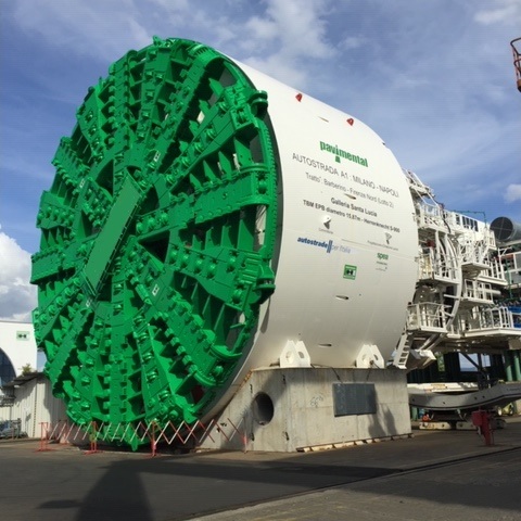
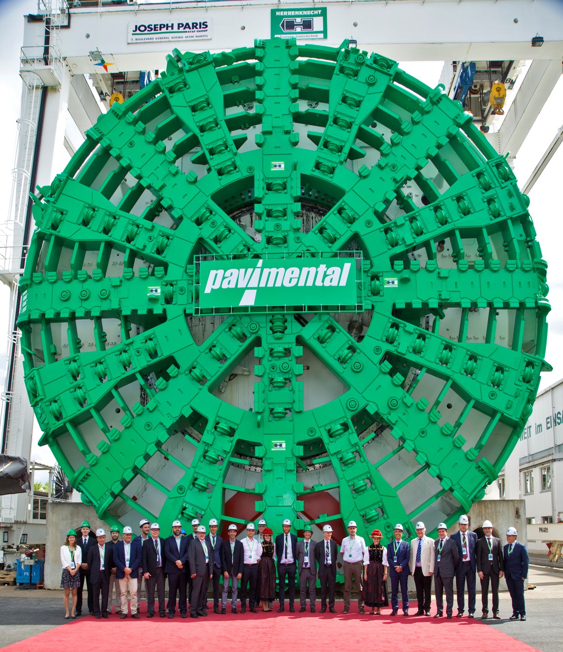
Excavation using a closed-front shield tunnel boring machine (TBM) for the construction of the Santa Lucia Tunnel – A1 Highway Milan – Naples – Barberino di Mugello – Florence North Stretch
.jpg)
Start date of the works for Lot 2: 15 March 2016
Timeframe for completion: 1,852 days
Basic bid value of the contract: 423,702,519.38 Euros
Project Description
The project for the expansion of the Barberino di Mugello – Florence North stretch of Barberino di Mugello – Incisa Valdarno to three lanes is being carried out between marker 261+503 (corresponding to the Barberino di Mugello exit) and marker 279+000 (about 700 metres South of the Calenzano/Sesto Fiorentino exit) on the current A1 Milan – Naples highway, and is part of the project for the enhancement of the highway between Sasso Marconi and Incisa Valdarno and is the initial Apennine stretch towards Florence, the most complex due to the morphology and environmental characteristics of the terrain involved.
The expansion of the highway stretch in question (17.5 km from marker 3+217 to marker 10+951) involves the construction of a new carriageway with 3 lanes plus an emergency lane in the South direction and the construction of a single tunnel 7.7 km long (Lot 2) called ‘Santa Lucia’, the function of which will be the ensure the single-direction flow of traffic on the highway stretch in question.
New Santa Lucia Tunnel
The new Santa Lucia Tunnel is constituted by a single bore, the naturally excavated part of which begins at marker 3+423.00 and ends at marker 19+971.00, covering a total distance of 7,548 metres; considering the covered stretch as well, which includes the artificial tunnels, this starts at marker 3+395.73.00 and ends at marker 11+120.0, covering a total distance of 7,724.27 metres.
The platform is constituted by three lanes 3.75 m wide and two verges 0.70 m wide. The marginal element on the left is constituted by a redirecting profile and on the right by a non-surmountable pavement with a minimum width of 60 cm, so as to constitute a protected route for exiting vehicles in the event of faults.
The Tunnel will be constructed with the help of an earth pressure balance shielded tunnel boring machine called TBM – EPB. The thickness of the surfacing is 55 cm and the cross-section of the tunnel has a diameter of 15.40 m, while the cross-section of the excavation and the TBM head has a diameter of 15.935 m and a cross section of about 200 m2.
The progression process of the TBM will enable the realization of a perfectly circular excavation and the definitive surfacing to be laid in the immediate vicinity of the excavation area. The surfacing is constituted by rings of about two metres in a longitudinal direction, in turn divided into shells. Using the so-called “universal ring” method, in which all of the rings are equal in length but with slightly varying widths (slightly trapezoidal panels), the rotation of the rings enables the realization of the planimetric and altimetric bends.
Tunnel Boring Machine S900
Earth Pressure Balance Machines (EPBMs) basically involve the head of the machine bearing utensils carrying out the excavation work and that the head is kept in place by the earth being excavated which, suitably conditioned, is kept under pressure within the excavation chamber by:
- the jacks pushing the shield, which transfer the pressure to the diaphragm separating the shield and the excavation chamber and, consequently, the earth excavated (equilibrium of forces);
- setting the rotation speed of the screw for the extraction of the material excavated (equilibrium of volume). Setting the extraction speed of the waste from the excavation chamber is a fundamental means of controlling the setting of the pressure levels on the head during excavation.
This type of TBM is generally constituted by:
Ø a rotating head (with utensil holders)
Ø a protective shield
Ø a thrust system of using longitudinal jacks balancing on the prefabricated shell surfacing
Ø a system of laying the prefabricated shells (erector) and all of the additional services on the rear back-up trucks.
Earth pressure balance shields were developed for use on soft cohesive terrain and are capable of supporting the head through earth pressure balance (EPBMs), in other words with the excavation chamber kept under pressure using the same material excavated, suitably conditioned. A bulkhead separates the tunnel from the rear part of the shield where the excavating head acts, delimiting the so-called “excavation chamber”. This basically causes an “accumulation” of material in the excavation chamber, controlling its extraction and measuring the consequent “earth pressure” using suitable pressure sensors, ensuring that its value is kept in compliance with the requirements deriving from the stability calculations. The support pressure must balance the pressure exercised by the terrain and that exercised by the waste water. The main field of application is on terrain with limited or no self-support capacity.
In the specific case of the Santa Lucia Tunnel, the following main lithological formations were be crossed alternately:
Monte Morello Formation, a formation of a flyschoidal nature constituted by an alternation of chalk, chalk marl, marl and siltstone, with a total length of the stretches in question of about 5,750 metres, or76.5%
Sillano Formation, a complex formation constituted by an alternation of prevalent clay, marl, sandstone, siltstone and chalk, with a total length of the stretches in question of about 582 metres, or 7.7%
Sillano Litofacies Arenacea Formation, an alternation of chalk, sandstone, marl and clay, with a total length of the stretches in question of about 743 metres, or 9.2%
Marl-chalk Sillano Litofacies Formation, an alternation of marl, clay, sandstone and chalk, with a total length of the stretches involved of about 510 metres, corresponding to 6.7%
The conditioning of the waste is done by injecting at the front (in front of the cutter head) or other points of the excavation chamber or screw specific products (foams and/or polymers, bentonite, etc.). This process enables the creation of a sort of “paste” which facilitates the management of the pressure within the excavation chamber, and also the correct use of the shell during the extraction process. The resulting material, once extracted from the excavation chamber through the screw (which is also the means of setting and controlling the quantity of material extracted) is removed from the tunnel using a system of conveyor belts.
To indirectly check whether there has been any dangerous excess excavation, especially in non-cohesive materials, the TBM is equipped with a system of scales which record the weight of the material extracted,. Although there is a certain margin of uncertainty of evaluating the specific density of the materials excavated (required in order to transfer from weight to volume extracted), the scales enable the weights to be controlled statistically, immediately highlighting any anomalies, which must be carefully studies and promptly resolved on the basis of the geology and support pressure on the head.
The following are also important parameters for detecting any anomalies during excavation:
Ø Support pressure on the head (working pressure in the excavation chamber, provided by earth pressure sensors)
Ø Value of the “apparent density” of the material in the excavation chamber, required to determine the gradient of the support pressure on the head.
Ø Injection pressure and volume of the two-component mixture, injected from surface level
Ø Head coupling
Ø Penetration factor
Behind the shield, the coating in prefabricated shells is assembled and the “annular vacuum” between the outer ring of the shells and the longitudinal grouting or backfilling is filled. Lastly, all of the auxiliary devices and systems required for continuing the excavation activities are concentrated in the back-up trucks at the rear.